The Four-Stroke Cycle of the Internal Combustion Engine
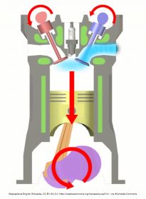
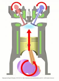
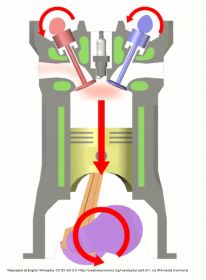
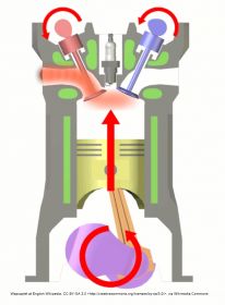
2. SQUASH: Both valves are closed. The fuel/air mixture is compressed by the piston movement back towards the top of the cylinder.
3. BANG: A spark ignites the mixture causing an explosion which violently throws the piston towards the bottom of the cylinder.
4. PUFF: Momentum throws the piston back towards the top. Exhaust valve is open hence the waste gases are forced out of the exhaust pipe.
That's about it and the cycle repeats!
Note that the initial momentum to start the cycle is provided by the battery/starter motor.
Step 3 is the 'power' provider and it provides the momentum for steps 1, 2 and 4
The SU Carburettor (Herbert Skinners 1904 Masterpiece!)
Many of the historic cars we drive are fitted with the SU carburettor and many of us will have tried to give the impression that we understand how they work while secretly being baffled by their mysterious components. I confess that I include myself in that group. I therefore set myself the target of genuinely learning how they work and of documenting it in simple terms. Here goes!
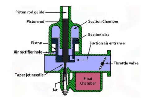
Lets have a look at one first:
Warning. This will be a Mickey Mouse description!
When the piston flies down the cylinder with the exhaust valve closed and the inlet valve open air will be pulled into the cylinder through the choke (the blue area) past the throttle valve ie from left to right on diagram. The volume of air allowed to enter is controlled by the throttle valve. The air movement will do two things. 1. Fuel will be sucked up into the choke via the jet and mixed with the air (“atomised”) and 2. A partial vacuum will be created in the suction chamber which will cause the piston to rise hence the taper jet needle will rise allowing more fuel into the petrol/air mixture which enters the cylinder.
For any given throttle opening and engine workload, a balance will be achieved between piston height and air volume movement. The greater the air volume movement the higher the engine power developed.
When more power is required, the throttle is opened further hence a greater volume of air will be pulled through the choke tube, the higher the piston/needle will lift and the more fuel will be aspirated because the needle is tapered.
When the engine is not required to move the car and is therefore just ticking over, the throttle valve is almost closed so minimal air is being drawn into the choke tube and there is insufficient vacuum in the suction chamber to lift the piston/needle so minimal fuel is aspirated.
A small dashpot is attached to the air piston and is topped up with SAE20 oil. A small fixed piston is in the oil. Its function is to provide a resistance to the upward movement of the air piston. This in turn delays the upward movement of the air piston. Until the air piston reaches its balance position there will be a shortage of air in the fuel/air mixture ie it will be “rich” with fuel. This provides the additional power needed for acceleration. It replaces the 'accelerator' pump often seen on other types of carburettor. A one-way valve in the oil damper piston allows rapid dropping of the air piston when the throttle valve is closed. A calibrated spring additionally pushes the air valve down.
In order to start a cold engine we pull out the 'choke' or 'cold start' control on the car dash. This has two functions. 1. The jet is lowered a little thus allowing more fuel into the choke. The richer mixture will ease starting. 2. The throttle is opened a little.
Points of interest:
Will temporarily removing the oil damper piston make an engine easier to start? This is often thought to be the case but it is probably more likely to make the engine more difficult to start! This is because the dramatic reduction in resistance for the air piston to rise will prevent the enriching of fuel/air mixture which is the function of the oil damper.
On most SU carbs there is a tiny pin which can be used to lift the needle by a very small amount (about 1/32inch). On a warm engine this should cause an immediate increase in engine revs but only for a second after which the revs will fall back to normal. This indicates a correct fuel/air mixture ie the carb is 'tuned'. If when depressing the pin the engine revs decrease then the mixture is too weak. If the engine revs increase and stay there then the mixture is too rich.
To enrich the mixture rotate the jet assembly (nut or screw) clockwise (as viewed from above) to drop it down a little. To weaken the mixture rotate the jet assembly anticlockwise to raise it a little.
Ignition System
That compressed fuel/air mixture in the cylinder needs to be ignited at the right time in order initiate the biggest explosion possible!
The basic ignition system is comprised of coil, points, distributor and plugs.
Lets work backwards!!
The spark at the plug triggers the explosion hence the power stroke of the engine.
The spark represents a voltage spike of around 40,000volts which is supplied by the coil.
The high voltage spark is caused by a low voltage spike (12v) to the input of the coil.
The low voltage spike is caused by the rapid charge of a capacitor.
The capacitor charge is initiated by the opening of the points.
The above is repeated for each cylinder in turn and the function of the distributor (with its rotor arm) is to connect the coil output to the appropriate spark plug. Most of our 'classic' engines have four cylinders and the common firing order is 1,3,4,2
I think it can be stated without hesitation that the vast majority of difficulties with the engines of our historic vehicles are due to ignition problems. It is amazing how often owners found themselves struggling to fix elusive fuel problems for hours when in fact the problem was 'dirty points', worn rotor arm, bad connection to the coil or loose HT cable! (I speak from personal experience!)
Tip 1
When fault-finding you can bypass the rotor arm and distributor cap by simply connecting a spark plug directly to the output of the coil. No spark means the problem is the coil, points or a connecting wire. The presence of a spark means the problem is distributor cap, rotor arm or carbon pencil which feeds the rotor.Tip 2
Remember, the chances are that a stationary engine is left with the points closed. If the ignition is switched on then an electrical current will flow through the coil, through the points and back to the battery. The coil may overheat and be damaged.So... if the ignition needs to be switched on while some other electrical problem is diagnosed then a good tip is to protect the coil by temporarily removing one of its low voltage spade connectors.


